
Basements & foundation slabs
Installed before the slab is poured, with coordinated waterproofing at pile heads, sumps, penetrations and construction joints.
FOCUS / Continuity beneath the slabBUILT FOR BELOW GROUND
Match membrane specifications and details to the structure, groundwater conditions and construction sequence.
Installed before the slab is poured, with coordinated waterproofing at pile heads, sumps, penetrations and construction joints.
FOCUS / Continuity beneath the slabAssess pre-applied installation against the retaining structure and formwork arrangement. Plan fixing, corners, overlaps and terminations together.
FOCUS / Wall-to-slab transitionsView the side-wall application guide ↗Select the system to suit the structural form, joint layout and working conditions. Demanding water pressure or chemical exposure requires a separate suitability assessment.
FOCUS / Conditions and detailingSubways, tunnels, reservoirs, canals, landfills, sewage treatment facilities, metallurgical and chemical facilities, and underground floors and side walls of industrial and other buildings. Each use requires a compatible pre-applied design; water-contact, chemical-resistance or environmental suitability must be verified for the particular project.
INSTALLATION & DETAILING
Review installation steps, side-wall details and handling requirements for your selected membrane system.
APPLICATION GUIDANCE
The additional application sheet below covers side-wall vertical fixing and the roof-slab-to-wall lap. It does not define a complete method for general field seams, rolling pressure or working temperature. Confirm those requirements for the selected adhesive system; do not substitute the welded membrane’s parameters.
ADHESIVE HDPE · APPLICATION DETAIL
For the side-wall arrangement shown in the supplied application sheet, a metal termination bar secures the membrane termination before further protective brickwork is removed. The roof-slab membrane is then connected to the side-wall membrane and the completed lap is protected promptly.
| Item | Requirement | Application note |
|---|---|---|
| Screws | Stainless steel · Ø 5.5 × 50 mm | Corrosion-resistant fixings |
| Metal termination bar | 25 × 2000 mm · 1.0 mm thick | The text specifies galvanised steel; see the coating note below. |
| Fixing spacing | 200 mm centres | Along the strip securing the membrane termination |
| Fixing position | 20 mm from the membrane end | Follow the position illustrated in the supplied detail. |
| Further brickwork removal | No more than 300 mm | Preferably the required lap length plus 150 mm |
| Effective slab-to-wall lap | At least 100 mm | Between the roof-slab and side-wall waterproofing membranes |
| Optional staged working | 10 m per section | Protect each completed section promptly. |
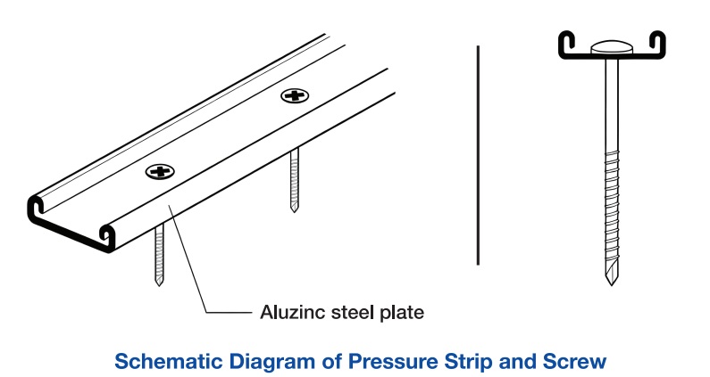
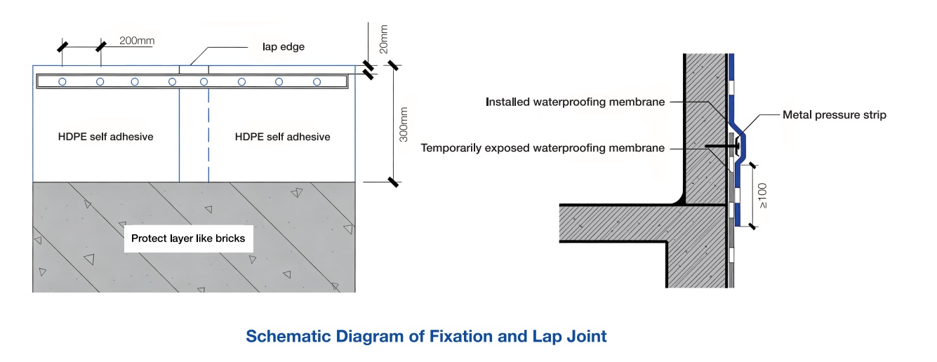
These requirements describe the side-wall fixing and roof-slab connection shown here. They are not general overlap dimensions for every adhesive HDPE joint. The source text calls the pressure strip “galvanised steel”, while the drawing labels it “Aluzinc steel plate”; confirm the required coating and compatible fixing specification before procurement.
APPLICATION GUIDANCE
The original sheet does not provide complete speed units. Obtain a confirmed welding procedure for the selected membrane and equipment. Establish temperature and travel speed using trial welds under actual site conditions; do not use incomplete example values as machine settings.
The supplied installation page requires an ambient temperature of at least 5°C and excludes rain, snow and winds above Beaufort force 5. Keep the base flat and protect completed areas from contamination that could affect concrete bonding. Follow these weather restrictions when planning installation.
BOTH MEMBRANE SYSTEMS
Storage, handling and quality requirements from the supplied product sheets apply to both ranges unless a confirmed product instruction states otherwise.
For horizontal storage, the source limits stacking to five layers. For vertical storage, keep rolls in a single layer. Separate different product types and specifications to avoid incorrect use.
Keep rolls away from direct sunlight and rain, and store them in a well-ventilated area. Maintain a storage temperature no higher than 45°C, and relative humidity no higher than 80%, as stated in the supplied sheets.
The product sheet specifies a shelf life of one year from the date of manufacture under normal storage conditions, with reinspection and confirmation of suitability after that period. This storage period is not an installed waterproofing warranty.
QUALITY & SAFETY
Read the applicable safety instructions. Inspect the membrane surface, overlaps and details; repair defects and protect completed work from damage or contamination. Contact Hongyuan’s technical team for construction and safety questions.